ad9361原理和配置

AD9361的收发通道讲解

AD9361 是 ADI 推出的面向 3G 和 4G 基站应用的高性能、高集成度的射频解决方案。
该器件集 RF前端与灵活的混合信号基带部分为一体,集成频率合成器,为处理器提供可配置数字接口。 AD9361 接收器 LO工作频率范围为 70 MHz 至 6.0 GHz,发射器 LO工作频率范围为 47 MHz 至 6.0 GHz,涵盖大部分特许执照和免执照频段,支持的通道带宽范围为 200 kHz 以下至 56 MHz。

在这里插入图片描述

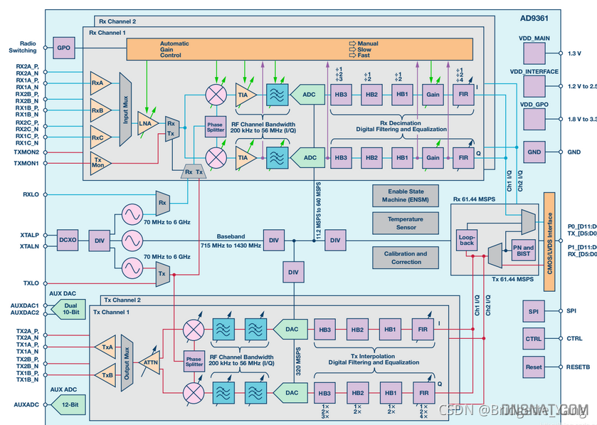
两个独立的直接变频接收器拥有首屈一指的噪声系数和线性度。每个接收 (RX)子系统都拥有独立的自动增益控制 (AGC)、直流失调校正、正交校正和数字滤波功能,从而消除了在数字基带中提供这些功能的必要性。 AD9361 还拥有灵活的手动增益模式,支持外部控制。每个通道搭载两个高动态范围模数转换器 (ADC),先将收到的 I信号和 Q 信号进行数字化处理,然后将其传过可配置抽取滤波器和 128 抽头有限脉冲响应 (FIR)滤波器,结果以相应的采样率生成 12 位输出信号。

滤波器配置

它支持 2x2 MIMO 通信,收发各有两条独立的射频通路。
接收通道如下:

在这里插入图片描述

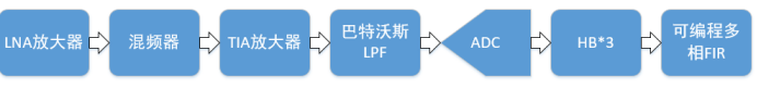
(1)LNA低噪声放大器:由于射频接收到的信号,有可能为微小信号,为了便于之后的数字处理,通过它将信号进行一定量的放大。
需要低噪声原因:噪声系数可以表示经过器件或者系统后信噪比的恶化程度,其等于输入信噪比与输出信噪比的比值,计算公式如下:

在这里插入图片描述

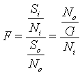
噪声系数是一个数字,通过它可以指定放大器或无线接收器的噪声性能。可以从放大器的信噪比开始。当信号通过任何微波组件时,噪声比信号功率增加得多,这种附加的噪声是由放大器本身产生的。信噪比总会下降。我们常用噪声系数表征放大器产生的噪声量。
如果器件引入的噪声大小是恒定的,那输入噪声为:

在这里插入图片描述

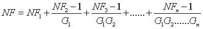
其中F是接收到的噪声因子,F1是第一个设备的噪声因子,G1是第一个设备线性单位的增益和损耗,F2是第一个设备的噪声因子,G2是第二个设备线性单位的增益或损耗
这时就可以看出第一级的噪声系数对整个级联影响最大,所以在整个系统的第一级要采用低噪声放大器。

(2)混频器:该混频器的中心频率范围为7MHz-6GHz,即可以处理的信号中频范围。通过这里可以将信号转换到零中频,便于后期处理的时候节省带宽。

(3)TIA放大器和低通滤波器:在模拟域进行一次滤波,在视频接收到的信号中,会有许多干扰信号及无关信号,如果直接进行ADC采样,有可能会将我们感兴趣的信号淹没,这时通过两个滤波器将感兴趣的信号以外的信号滤掉,同时可以滤除在信道传输过程中的噪声。

(4)ADC正交采样:采用正交采样,可以减少带宽的使用率,采样完成后将其转化为数字域处理。

(5)三个半波滤波器:采样后再进行一轮滤波,采用半波滤波器的原因是它的系数是对称的,并且有一半的系数为零,可以大大的降低运算量即减少乘法器的个数。而采用三个的原因是半波滤波器的性能不好,抽取的次数不能很多,分次来进行滤波对整体系统影响更小。

(6)FIR滤波器:最后再经过一个常规的FIR滤波器,但其抽取倍数也不会很大。
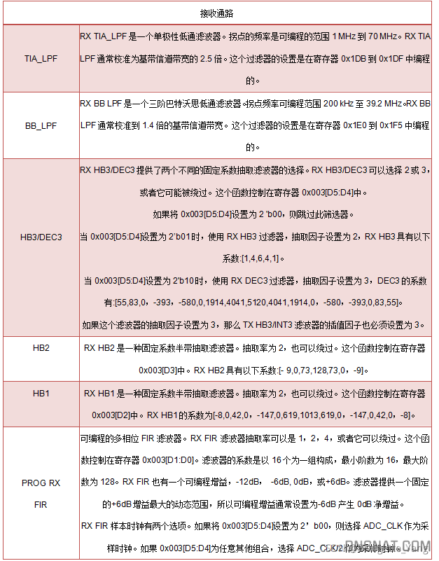
接收通道中各滤波器的配置表格如下所示:

在这里插入图片描述

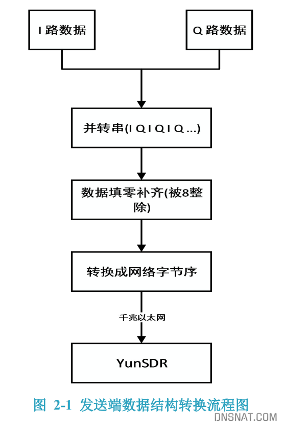
发送端如下图所示(与接收通道的分析类似):

在这里插入图片描述

Tx信号路径从AD9361数字接口接收12位二进制补码I-Q格式的数据,每个通道(I和Q)通过四个数字插值滤波器将该数据传递到12位DAC。四个插值滤波器中的每一个都可以被旁路。在进入射频混频器之前通过两个低通滤波器,ad9361_set_tx_rf_bandwidth函数可对每个低通滤波器LPF的角点频率进行编程。

可编程数字滤波器提供了从数字到模拟转换之前所需的带宽限制,还可以对数据进行插值,从数字接口输入数据速率转换为DAC转换所需的速率,在每个滤波器中,首先进行插值,再滤波。
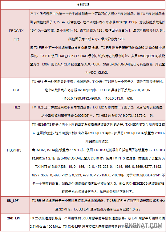
发送通道中各滤波器的配置表格如下所示:

在这里插入图片描述

image-20240909174453161

matlab单音信号生成

1
2
3
4
5
6
7
8
9
10
11
12
13
14
15
16
17
18
19
20
21
22
23
24
25
26
27
28
29
30
31
32
33
34
35
36
37
38
39
40
41
42
43
44
45
46
47
48
49
50
51
52
53
54
55
56
57
58
59
60
61
62
63
64
65
66
67
68
69
70
71
72
73
74
75
76
77
78
79
80
81
82
83
84
85
86
87
88
89
90
91
92
93
94
% 参数设置
sampleRate = 20*1000*1000; % 采样率20Mhz
sampleNum = 8;
numSamples = 1024; % 样本数量
numSingle = numSamples / sampleNum; % 单个样本
freq = 1;

% 生成随机I信号和Q信号
%I = randn(numSamples, 1); % 生成随机I信号
%Q = randn(numSamples, 1); % 生成随机Q信号

%% generate tone signal
I=round(cos(2*freq*pi/numSingle*[0:(numSingle -1)]).*9830);
Q=round(sin(2*freq*pi/numSingle*[0:(numSingle -1)]).*9830);


%-----载波扩展,长度和data_trans相等-----%
I=repmat(I, 1, sampleNum);
Q=repmat(Q, 1, sampleNum);

% 生成IQ信号
IQ = I + 1j*Q; % I和Q合成为复数信号

% 可视化IQ信号的幅度谱和相位谱
figure;
plot(I);
title('I信号');
xlabel('时间');
ylabel('幅度');

figure;
plot(IQ);
title('IQ信号');
xlabel('时间');
ylabel('幅度');

% 如果需要,可以通过FFT分析IQ信号的频谱
IQ_fft = fft(IQ);
IQ_fft_abs = abs(IQ_fft);
IQ_fft_phase = angle(IQ_fft);

% 可视化IQ信号的幅度谱和相位谱
figure;
spectrum = fftshift(IQ_fft_abs);
freq = (-numSamples/2:numSamples/2-1)/numSamples*sampleRate;
plot(freq, spectrum);
title('IQ信号的幅度谱');
xlabel('频率 (Hz)');
ylabel('幅度');

figure;
phase_spectrum = fftshift(IQ_fft_phase);
plot(freq, phase_spectrum);
title('IQ信号的相位谱');
xlabel('频率 (Hz)');
ylabel('相位 (弧度)');

%% iq mux
txdatas=zeros(1,length(IQ)*2);
txdatas(1:2:end)=real(IQ);
txdatas(2:2:end)=imag(IQ);

%% add pad
rem=-1;
i=0;
while (rem<0)
rem=1024*2^i-length(txdatas);
i=i+1;
end
txdata1=[txdatas zeros(1,rem)];

%%补码表示
txd1=(txdata1<0)*65536+txdata1;

%%并转串
txd2=dec2hex(txd1,4);
txd3=txd2(:,1:2);
txd4=txd2(:,3:4);
txd5=hex2dec(txd3);
txd6=hex2dec(txd4);
txd7=zeros(length(txd6)*2,1);
txd7(1:2:end)=txd6;
txd7(2:2:end)=txd5;

% 串转4字节数组
for i = 1:1024
j = i*4;
txd8(i) = txd7(j)*16777216 + txd7(j - 1)*65536 + txd7(j - 2)*256 + txd7(j - 3);
end

fid=fopen('D:\data1.c','wt');%写入文件路径
for i=1:1:length(txd8)
fprintf(fid,'0x%08x,\n',txd8(i));
end

配置参数

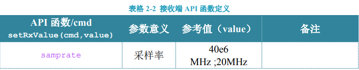
​ 对数据结构有所了解后,则需要对 YunSDR 进行射频参数配置等操作,在参数配置 过程中需要使用若干 API 函数,表 1 给出了发端的 API 配置函数,主要包括函数名、具 体配置命令、参数意义、常用参考值以及注意事项。

image-20240909141906474

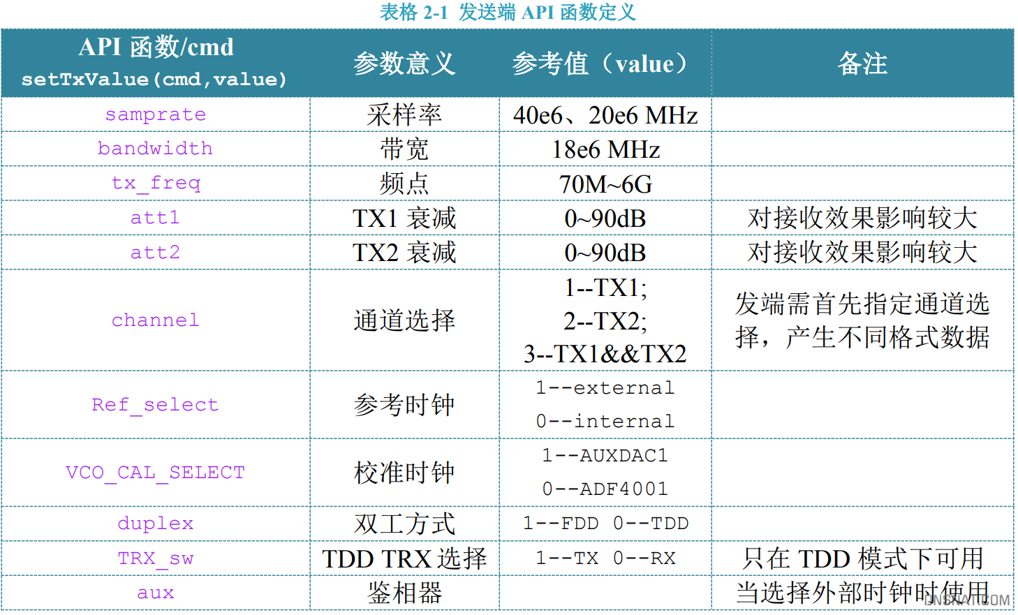
在本实验中,设置采样率为 40MHZ,带宽为 18MHZ,射频频点为 1.5GHZ,两个发送 通道 tx1 和 tx2 的发送衰减为 30000mdb。参考代码如下:

1
2
3
4
5
6
samp_hex=dec2hex(40e6,8);  		%采样率
bw_hex=dec2hex(18e6,8); %带宽
freq_hex=dec2hex(1500e6,10); %射频频点
tx_att1=dec2hex(30000,8);
tx_att2=dec2hex(30000,8);
tx_chan=3; %1=tx1;2=tx2;3=tx1&tx2

对于接收端需要配置的参数较少,具体如表 2:
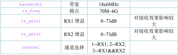
image-20240909142016707

image-20240909142034866

接收端的配置如下:

1
2
3
4
5
6
7
samp_hex=dec2hex(40e6,8);
bw_hex=dec2hex(18e6,8);
freq_hex=dec2hex(1500e6,10); %%for ad9361
rxgain1=5;
rxgain2=5;
rx_chan=3; %1=rx1;2=rx2;3=rx1&rx2
cyc=1;

AD9361 的参考时钟配置

​ AD9361 的参考时钟由本地 TCX0 与外部或 GPS 同步时钟鉴相获得。由于本实验为 自收发单音信号实验,所以采用内部参考时钟。当选择内部参考时钟(REF_SELET=0) 时,使用 ADF4001 鉴相器进行校准(VCO_CAL=0)。外部参考时钟 refrerence 和 vctcxo 时钟 vc-clock 分别进行分频,分频后鉴相,将 CP 电压输出给 VC-TCXO 的压控端,当 ADF4001 锁定后 VC-TCXO 与外部参考的基准时钟严格同频。假设外部参考 10MHz,本 地晶振 26MHz,rcount 表示参考频频系数,ncount 表示本地时钟分频系数,令 rcount=10, ncount=26 可以完成 ADF4001 的鉴相功能。参考代码如下:

1
2
3
4
5
6
7
rcount=dec2hex(10,4); 			% reference clock divide
ncount=dec2hex(26,4); % internal vctcxo divide
ref_hex=dec2hex(0,8); % 1=external ref 0=internal ref
vco_cal_hex=dec2hex(1,8); % 1=auxdac 0=reference clock
aux_dac1_hex=dec2hex(0,8);
fdd_tdd_hex=dec2hex(1,8);
trx_sw_hex=dec2hex(1,8);

ASK 调制/解调实验

​ 发送端,我们直接发送调制好的 2ASK 信号。由上述原理可知,当基带信号为 0 时, 不发送载波(设为 0);当基带信号为 1 时,发送归一化频率为 fs 的载波信号。 设 AD9361 工作的射频频点为 fc ,调制载波的频率为 fs ,则调制信号 2ASK 经过上变 频到射频之后射频发送的信号频率应为 0 f = fc + fs 。若令 fs = 1MHZ, fc = 999MHZ,则射频输出信号中心频率应为 1GHZ。参考代码如下

1
2
samp_hex=dec2hex(20e6,8);		%采样率
freq_hex=dec2hex(999e6,10); %射频频点

当基带信号为 1 时,我们需要发送频率为 fs = 1MHZ 的正交调制载波信号,那么如何发送呢?设 AD9361 的采样频率为 samp f ,则在一个完整的载波周期中所包含的采样点的个数应为:n= samp f / fs 。本实验中令 samp f =20MHZ,则 n=20。也就是说,我们需要产生20 个 IQ 正交数据点才能恢复出一个完整的载波周期。参考代码如下:

1
2
3
%-----产生 I、Q 两路载波信号,并量化-----%
carrier_I=round(cos(2*pi/20*[0:19]).*30000);
carrier_Q=round(sin(2*pi/20*[0:19]).*30000);

当我们产生随机的二进制码流之后,根据键控法的基本思想,每个码元的宽度必须和载波周期相同,以上分析可知,我们产生的载波一个周期为 20 个数据点,因此我们必须将原始码流的每一位扩展为 20 位,参考代码如下

1
2
3
4
5
6
7
8
9
%-----数据源数量-----%
bit_Num = 500;
%-----每个码元占据 20 个采样点,20M 采样率下为 1M-----%
bit_Width = 20;
%-----产生随机数据帧,length=500-----%
bit_trans = randint(1,bit_Num);
%-----数据扩展,每个码元扩展为 20 位-----%
tmp1 = repmat(bit_trans',1,bit_Width);
data_trans = reshape(tmp1',1,length(tmp1).*bit_Width);

若我们产生 500bit 的原始流,经 20 倍扩展之后的数据量为 500*20=10000bit。 因此,我们也需要将载波扩展为 10000bit,参考代码如下:

1
2
3
4
5
6
%-----载波扩展,长度和 data_trans 相等-----%
carrier_I=repmat(carrier_I,1,bit_Num);
carrier_Q=repmat(carrier_Q,1,bit_Num);
carrier=carrier_I+1i*carrier_Q;
%-----键控2ASK信号调制-----%
mod_data=data_trans.*carrier;

至此,我们直接用键控法进行 2ASK 调制,即让原始二进制码元和载波直接相乘,即可得到 2ASK 已 调信号。我们可以画出调制好的信号 mod_data

1
2
3
4
5
6
7
8
9
10
11
12
13
14
15
16
17
18
19
20
21
22
23
24
25
26
27
28
29
30
31
32
33
34
35
36
37
38
39
40
41
42
43
44
45
46
47
48
49
50
51
52
53
54
55
56
57
58
59
60
61
62
63
64
65
66
67
68
69
70
71
72
73
74
75
76
77
78
79
80
81
82
83
84
85
86
87
88
89
90
91
92
93
94
95
96
97
98
99
100
101
102
103
104
105
106
107
108
109
110
111
112
113
114
115
116
117
118
119
120
121
122
123
124
125
126
127
128
129
130
131
132
133
134
135
136
137
138
139
140
141
142
143
144
clc;
clear all;
close all;
warning off;
%****************ht7600*******************//
%ref_hex 1=external ref;0=internal ref
%vco_cal_hex 1=AUXDAC1;0=ADF4001
%fdd_tdd_hex 1=FDD 0=TDD
%trx_sw_hex 1=TX 0=RX
%****************ht7600*******************//
rcount=dec2hex(10,4);%reference clock divide
ncount=dec2hex(26,4);%internal vctcxo divide
ref_hex=dec2hex(0,8);%1=external ref 0=internal ref
vco_cal_hex=dec2hex(1,8);%1=auxdac 0=reference clock
aux_dac1_hex=dec2hex(0,8);
fdd_tdd_hex=dec2hex(1,8);
trx_sw_hex=dec2hex(1,8);

samp_hex=dec2hex(20e6,8);
bw_hex=dec2hex(18e6,8);
freq_hex=dec2hex(2140e6,10); %%for ad9361
tx_att1=dec2hex(30000,8);
tx_att2=dec2hex(30000,8);
tx_chan=1;%1=tx1;2=tx2;3=tx1&tx2
%=====以下为数据调制部分=====%
%-----数据源数量-----%
bit_Num = 500;
%-----每个码元占据20个采样点,20M采样率下为1M-----%
bit_Width = 20;
%-----产生随机数据帧,length=500-----%
bit_trans = randi(1,bit_Num);
%-----数据扩展,每个码元扩展为20位-----%
tmp1 = repmat(bit_trans',1,bit_Width);
data_trans = reshape(tmp1', length(bit_trans), []);
%-----产生I、Q两路载波信号,并量化-----%
carrier_I=round(cos(2*pi/20*[0:19]).*30000);
carrier_Q=round(sin(2*pi/20*[0:19]).*30000);
%-----载波扩展,长度和data_trans相等-----%
carrier_I=repmat(carrier_I,1,bit_Num);
carrier_Q=repmat(carrier_Q,1,bit_Num);
carrier=carrier_I+1i*carrier_Q;
%-----键控2ASK信号调制-----%
mod_data=data_trans.*carrier;
%-----创建帧同步训练序列-----%
[training]=creat_training();
%-----数据组帧-----%
txdata=[training mod_data];
disp(txdata);
%==========================================%
%% copy to 2chanel
if tx_chan==1 || tx_chan==2
txdata2=txdata;
elseif tx_chan==3
txdata2=zeros(1,length(txdata)*2);
txdata2(1:2:end)=txdata;
txdata2(2:2:end)=txdata;
end
%% iq mux
txdatas=zeros(1,length(txdata2)*2);
txdatas(1:2:end)=real(txdata2);
txdatas(2:2:end)=imag(txdata2);
%% add pad
rem=-1;
i=0;
while (rem<0)
rem=1024*2^i-length(txdatas);
i=i+1;
end
txdata1=[txdatas zeros(1,rem)];
txd1=(txdata1<0)*65536+txdata1;
txd2=dec2hex(txd1,4);
txd3=txd2(:,1:2);
txd4=txd2(:,3:4);
txd5=hex2dec(txd3);
txd6=hex2dec(txd4);
txd7=zeros(length(txd6)*2,1);
txd7(1:2:end)=txd6;
txd7(2:2:end)=txd5;


%% open control port
ctrl_link = udp('192.168.1.10', 5006);
fopen(ctrl_link);
%% open data port
data_link = tcpip('192.168.1.10', 5005);
set(data_link,'InputBufferSize',64*1024);
set(data_link,'OutputBufferSize',64*1024);
fopen(data_link);
%% tx samp rate
samp=[0 5 hex2dec('22') hex2dec('f0') hex2dec(samp_hex(7:8)) hex2dec(samp_hex(5:6)) hex2dec(samp_hex(3:4)) hex2dec(samp_hex(1:2))];
fwrite(ctrl_link,samp,'uint8');
%% tx bandwidth rate
bw=[0 7 hex2dec('22') hex2dec('f0') hex2dec(bw_hex(7:8)) hex2dec(bw_hex(5:6)) hex2dec(bw_hex(3:4)) hex2dec(bw_hex(1:2))];
fwrite(ctrl_link,bw,'uint8');
%% send tx freq set cmd
tx_freq=[hex2dec(freq_hex(1:2)) 3 hex2dec('22') hex2dec('f0') hex2dec(freq_hex(9:10)) hex2dec(freq_hex(7:8)) hex2dec(freq_hex(5:6)) hex2dec(freq_hex(3:4))];
fwrite(ctrl_link,tx_freq,'uint8');
%% send tx vga set cmd
tx_vga=[0 9 hex2dec('22') hex2dec('f0') hex2dec(tx_att1(7:8)) hex2dec(tx_att1(5:6)) hex2dec(tx_att1(3:4)) hex2dec(tx_att1(1:2))]; %TX1
fwrite(ctrl_link,tx_vga,'uint8');
tx_vga=[0 11 hex2dec('22') hex2dec('f0') hex2dec(tx_att2(7:8)) hex2dec(tx_att2(5:6)) hex2dec(tx_att2(3:4)) hex2dec(tx_att2(1:2))]; %TX2
fwrite(ctrl_link,tx_vga,'uint8');
%% send tx channel set cmd
channel=[tx_chan 0 hex2dec('20') hex2dec('f0') 0 0 0 0];
fwrite(ctrl_link,channel,'uint8');
%% custom rf control command
% adf4001 config
adf4001=[0 40 hex2dec('18') hex2dec('f0') hex2dec(ncount(3:4)) hex2dec(ncount(1:2)) hex2dec(rcount(3:4)) hex2dec(rcount(1:2))];
fwrite(ctrl_link,adf4001,'uint8');
% ref_select
ref_select=[0 40 hex2dec('22') hex2dec('f0') hex2dec(ref_hex(7:8)) hex2dec(ref_hex(5:6)) hex2dec(ref_hex(3:4)) hex2dec(ref_hex(1:2))];
fwrite(ctrl_link,ref_select,'uint8');
% vco_cal_select
vco_cal_select=[0 41 hex2dec('22') hex2dec('f0') hex2dec(vco_cal_hex(7:8)) hex2dec(vco_cal_hex(5:6)) hex2dec(vco_cal_hex(3:4)) hex2dec(vco_cal_hex(1:2))];
fwrite(ctrl_link,vco_cal_select,'uint8');
% fdd_tdd_select
fdd_tdd_select=[0 42 hex2dec('22') hex2dec('f0') hex2dec(fdd_tdd_hex(7:8)) hex2dec(fdd_tdd_hex(5:6)) hex2dec(fdd_tdd_hex(3:4)) hex2dec(fdd_tdd_hex(1:2))];
fwrite(ctrl_link,fdd_tdd_select,'uint8');
% trx_sw
trx_sw=[0 43 hex2dec('22') hex2dec('f0') hex2dec(trx_sw_hex(7:8)) hex2dec(trx_sw_hex(5:6)) hex2dec(trx_sw_hex(3:4)) hex2dec(trx_sw_hex(1:2))];
fwrite(ctrl_link,trx_sw,'uint8');
% aux_dac1
aux_dac1=[0 44 hex2dec('22') hex2dec('f0') hex2dec(aux_dac1_hex(7:8)) hex2dec(aux_dac1_hex(5:6)) hex2dec(aux_dac1_hex(3:4)) hex2dec(aux_dac1_hex(1:2))];
fwrite(ctrl_link,aux_dac1,'uint8');
%% send handshake cmd
handshake=[2 0 hex2dec('16') hex2dec('f0') 0 0 0 0];
fwrite(ctrl_link ,handshake, 'uint8');
%% send handshake2 cmd
data_length = dec2hex((2^(i-1)*2)*1024,8);
handshake=[2 0 hex2dec('17') hex2dec('f0') hex2dec(data_length(7:8)) hex2dec(data_length(5:6)) hex2dec(data_length(3:4)) hex2dec(data_length(1:2))];
fwrite(ctrl_link ,handshake, 'uint8');
%% Write data to the zing and read from the host.
fwrite(data_link,txd7,'uint8');
%% send handshake2 cmd to stop adc output
%handshake=[hex2dec('ff') 0 hex2dec('17') hex2dec('f0') 0 0 0 0];
%fwrite(ctrl_link,handshake,'uint8');
%% close all link
fclose(data_link);
delete(data_link);
clear data_link;
fclose(ctrl_link);
delete(ctrl_link);
clear ctrl_link;
disp('data tansfer done');

配置代码框架

matlab 通过udp直接配置开发板发送数据,配套服务端代码:YunSDR/Y210/Firmware/OS/Application at master · demonelf/YunSDR (github.com)

1
2
3
4
5
6
7
8
9
10
11
12
13
14
15
16
17
18
19
20
21
22
23
24
25
26
27
28
29
30
31
32
33
34
35
36
37
38
39
40
41
42
43
44
45
46
47
48
49
50
51
52
53
54
55
56
57
58
59
60
61
62
63
64
65
66
67
68
69
70
71
72
73
74
75
76
77
78
79
80
81
82
83
84
85
86
87
88
89
90
91
92
93
94
95
96
97
/******************************************************************************/
/************************ Constants Definitions *******************************/
/******************************************************************************/
command cmd_list[] = {
{"help?", "Displays all available commands.", "", get_help},
{"register?", "Gets the specified register value.", "", get_register},
{"tx_lo_freq?", "Gets current TX LO frequency [MHz].", "", get_tx_lo_freq},
{"tx_lo_freq=", "Sets the TX LO frequency [MHz].", "", set_tx_lo_freq},
{"tx_samp_freq?", "Gets current TX sampling frequency [Hz].", "", get_tx_samp_freq},
{"tx_samp_freq=", "Sets the TX sampling frequency [Hz].", "", set_tx_samp_freq},
{"tx_rf_bandwidth?", "Gets current TX RF bandwidth [Hz].", "", get_tx_rf_bandwidth},
{"tx_rf_bandwidth=", "Sets the TX RF bandwidth [Hz].", "", set_tx_rf_bandwidth},
{"tx1_attenuation?", "Gets current TX1 attenuation [mdB].", "", get_tx1_attenuation},
{"tx1_attenuation=", "Sets the TX1 attenuation [mdB].", "", set_tx1_attenuation},
{"tx2_attenuation?", "Gets current TX2 attenuation [mdB].", "", get_tx2_attenuation},
{"tx2_attenuation=", "Sets the TX2 attenuation [mdB].", "", set_tx2_attenuation},
{"tx_fir_en?", "Gets current TX FIR state.", "", get_tx_fir_en},
{"tx_fir_en=", "Sets the TX FIR state.", "", set_tx_fir_en},
{"rx_lo_freq?", "Gets current RX LO frequency [MHz].", "", get_rx_lo_freq},
{"rx_lo_freq=", "Sets the RX LO frequency [MHz].", "", set_rx_lo_freq},
{"rx_samp_freq?", "Gets current RX sampling frequency [Hz].", "", get_rx_samp_freq},
{"rx_samp_freq=", "Sets the RX sampling frequency [Hz].", "", set_rx_samp_freq},
{"rx_rf_bandwidth?", "Gets current RX RF bandwidth [Hz].", "", get_rx_rf_bandwidth},
{"rx_rf_bandwidth=", "Sets the RX RF bandwidth [Hz].", "", set_rx_rf_bandwidth},
{"rx1_gc_mode?", "Gets current RX1 GC mode.", "", get_rx1_gc_mode},
{"rx1_gc_mode=", "Sets the RX1 GC mode.", "", set_rx1_gc_mode},
{"rx2_gc_mode?", "Gets current RX2 GC mode.", "", get_rx2_gc_mode},
{"rx2_gc_mode=", "Sets the RX2 GC mode.", "", set_rx2_gc_mode},
{"rx1_rf_gain?", "Gets current RX1 RF gain.", "", get_rx1_rf_gain},
{"rx1_rf_gain=", "Sets the RX1 RF gain.", "", set_rx1_rf_gain},
{"rx2_rf_gain?", "Gets current RX2 RF gain.", "", get_rx2_rf_gain},
{"rx2_rf_gain=", "Sets the RX2 RF gain.", "", set_rx2_rf_gain},
{"rx_fir_en?", "Gets current RX FIR state.", "", get_rx_fir_en},
{"rx_fir_en=", "Sets the RX FIR state.", "", set_rx_fir_en},
{"dds_tx1_tone1_freq?", "Gets current DDS TX1 Tone 1 frequency [Hz].", "", get_dds_tx1_tone1_freq},
{"dds_tx1_tone1_freq=", "Sets the DDS TX1 Tone 1 frequency [Hz].", "", set_dds_tx1_tone1_freq},
{"dds_tx1_tone2_freq?", "Gets current DDS TX1 Tone 2 frequency [Hz].", "", get_dds_tx1_tone2_freq},
{"dds_tx1_tone2_freq=", "Sets the DDS TX1 Tone 2 frequency [Hz].", "", set_dds_tx1_tone2_freq},
{"dds_tx1_tone1_phase?", "Gets current DDS TX1 Tone 1 phase [degrees].", "", get_dds_tx1_tone1_phase},
{"dds_tx1_tone1_phase=", "Sets the DDS TX1 Tone 1 phase [degrees].", "", set_dds_tx1_tone1_phase},
{"dds_tx1_tone2_phase?", "Gets current DDS TX1 Tone 2 phase [degrees].", "", get_dds_tx1_tone2_phase},
{"dds_tx1_tone2_phase=", "Sets the DDS TX1 Tone 2 phase [degrees].", "", set_dds_tx1_tone2_phase},
{"dds_tx1_tone1_scale?", "Gets current DDS TX1 Tone 1 scale.", "", get_dds_tx1_tone1_scale},
{"dds_tx1_tone1_scale=", "Sets the DDS TX1 Tone 1 scale.", "", set_dds_tx1_tone1_scale},
{"dds_tx1_tone2_scale?", "Gets current DDS TX1 Tone 2 scale.", "", get_dds_tx1_tone2_scale},
{"dds_tx1_tone2_scale=", "Sets the DDS TX1 Tone 2 scale.", "", set_dds_tx1_tone2_scale},
{"dds_tx2_tone1_freq?", "Gets current DDS TX2 Tone 1 frequency [Hz].", "", get_dds_tx2_tone1_freq},
{"dds_tx2_tone1_freq=", "Sets the DDS TX2 Tone 1 frequency [Hz].", "", set_dds_tx2_tone1_freq},
{"dds_tx2_tone2_freq?", "Gets current DDS TX2 Tone 2 frequency [Hz].", "", get_dds_tx2_tone2_freq},
{"dds_tx2_tone2_freq=", "Sets the DDS TX2 Tone 2 frequency [Hz].", "", set_dds_tx2_tone2_freq},
{"dds_tx2_tone1_phase?", "Gets current DDS TX2 Tone 1 phase [degrees].", "", get_dds_tx2_tone1_phase},
{"dds_tx2_tone1_phase=", "Sets the DDS TX2 Tone 1 phase [degrees].", "", set_dds_tx2_tone1_phase},
{"dds_tx2_tone2_phase?", "Gets current DDS TX2 Tone 2 phase [degrees].", "", get_dds_tx2_tone2_phase},
{"dds_tx2_tone2_phase=", "Sets the DDS TX2 Tone 2 phase [degrees].", "", set_dds_tx2_tone2_phase},
{"dds_tx2_tone1_scale?", "Gets current DDS TX2 Tone 1 scale.", "", get_dds_tx2_tone1_scale},
{"dds_tx2_tone1_scale=", "Sets the DDS TX2 Tone 1 scale.", "", set_dds_tx2_tone1_scale},
{"dds_tx2_tone2_scale?", "Gets current DDS TX2 Tone 2 scale.", "", dds_tx2_tone2_scale},
{"dds_tx2_tone2_scale=", "Sets the DDS TX2 Tone 2 scale.", "", set_dds_tx2_tone2_scale},
};


case SDR_CUSTOM_CMD:
{
unsigned char cmd = (cmd_buff[0]&0x0000FF00)>>8;
if(cmd >= 0 && cmd < 30) {
if(cmd == 3 || cmd == 15){
sdr_param[0] = (uint64_t)cmd_buff[1]|(((uint64_t)cmd_buff[0]&0x000000FF)<<32);
printf("freq = %llu\n", (uint64_t)sdr_param[0]);
}else{
sdr_param[0] = cmd_buff[1];
}

sdr_param_no = 1;
cmd_list[cmd].function(sdr_param, sdr_param_no);
if(device_type == SDR_DEVICE_Y310){
if(cmd == 3){
tx_band_sel((uint64_t)sdr_param[0]);
tx_rf_port_input_select((uint64_t)sdr_param[0]);
}
if(cmd == 15){
rx1_band_sel((uint64_t)sdr_param[0]);
rx2_band_sel((uint64_t)sdr_param[0]);
rx_rf_port_input_select((uint64_t)sdr_param[0]);
}
}
}
else if(cmd >= 40 && cmd <= 45) {
if(device_type == SDR_DEVICE_Y310){
custom_cmd_list[cmd-40].function(cmd_buff[1]);
}
}
else
dma_dbg(MSG_WARNING,"CMD:undefined command!\n");
dma_dbg(MSG_DEBUG,"CMD:recv SDR_CUSTOM cmd\n");
break;
}

image-20240913142053977

射频配置协议

vitis裸板示例:

https://github.com/analogdevicesinc/no-OS/blob/main/projects/ad9361

linux适配

参考:

  1. AD9363数据手册和产品信息 | Analog Devices

  2. V3X20yunSDR开发流程培训

  3. SDR无线通信实验讲义


ad9361原理和配置
http://blog.uanet.cn/FPGA/ad9361原理和配置.html
作者
dnsnat
发布于
2025年2月13日
许可协议